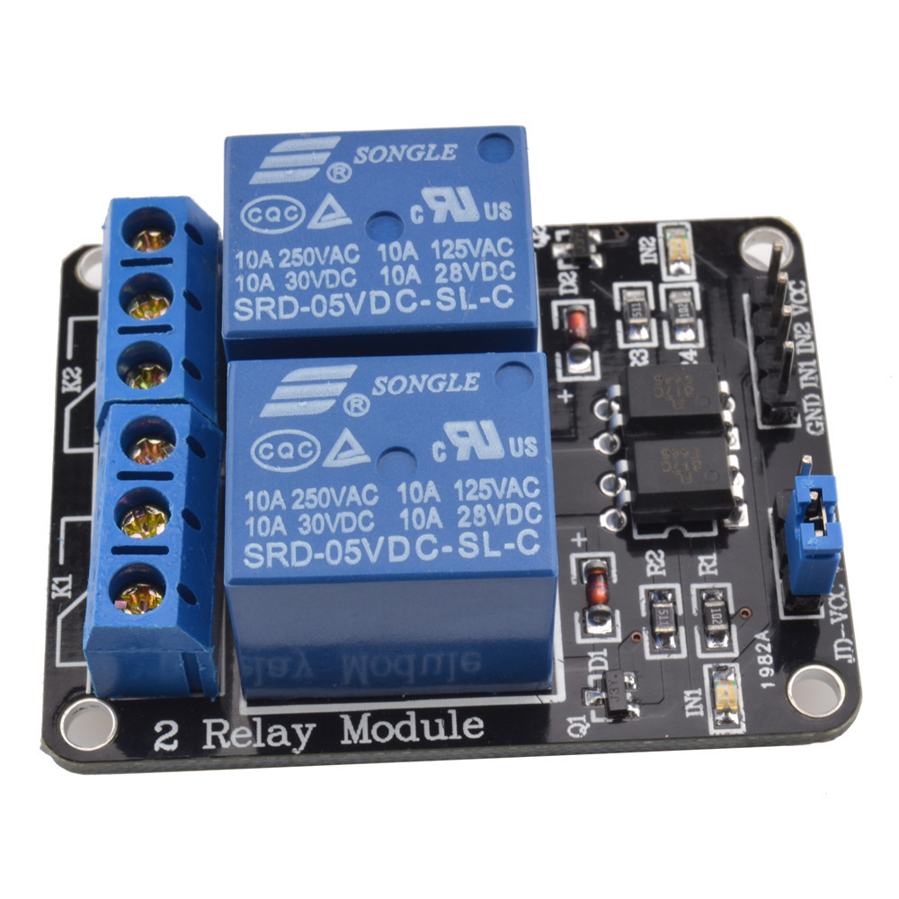
The 5V Dual Channel Relay Module with Optocoupler is designed to control various appliances and equipment with a large current using low-level trigger signals. It utilizes opto isolation circuitry to provide electrical isolation between the control signal and the relay switching circuit.
Arduino
PIC
ARM
8051
AVR
DSP
MSP430
TTL logic
Do not apply a voltage higher than 5V to the control pins (IN1, IN2).
Do not reverse the polarity when connecting power to the module.
Do not exceed the specified switching voltages and currents.
Connect power (5V and 0V) to the 1x4 pin header labeled VCC and GND respectively.
Control the relays using 3.3V or 5V logic signals from compatible microcontrollers.
Ensure correct jumper settings for desired trigger mode (high-level or low-level).
3.3V to 5V
5V
250V @ 10A
30V @ 10A
19.5
50.6
28
39